
Take one stage on its own, or hand us the component from drawing through to erection.
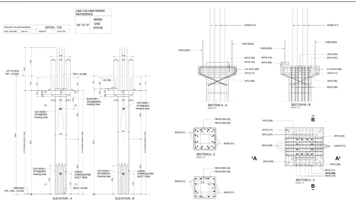
Detailing
Our technical department produces precast shop drawings and bar bending schedules from the consultant's design, and coordinates cast-in details, lifting points and connection hardware before anything reaches the mould shop.
Modelling
Every component is modelled before it is cast. Clashes between precast elements, reinforcement, cast-in services and connection hardware are found in the model rather than in the mould or on the crane hook, and the shop drawings come out of the model.
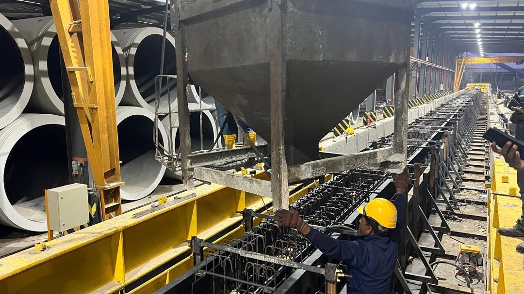
Casting
Factory-controlled casting, with turning tables for wall panels, cured to specified strength before demoulding. Columns and beams are produced under the factory production control verified by our CREAM product certificate.
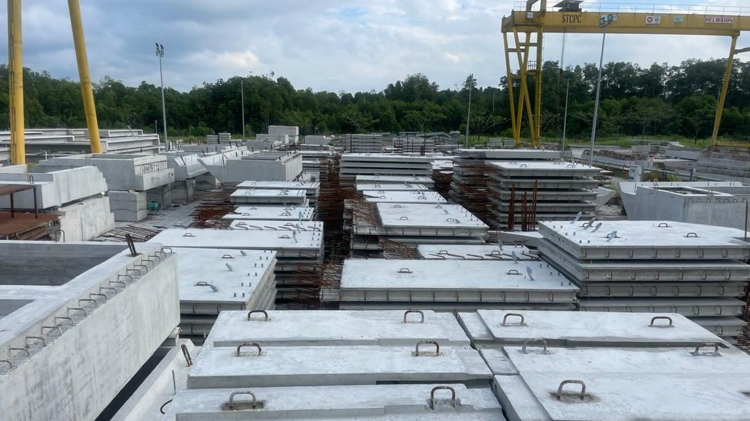
Delivery
Components are stacked in our own yard and released against the site erection programme, so deliveries arrive in lifting sequence rather than in casting sequence.
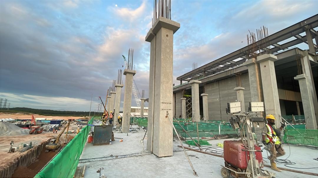
Erection
Our own lifting supervisors and erection crews set the components, with splice sleeve and grouting works as required.
Precast is usually the answer, because it is where budget and speed meet. Send us your preliminary drawings and we will come back with a scheme, connection details included. There is no charge for it.
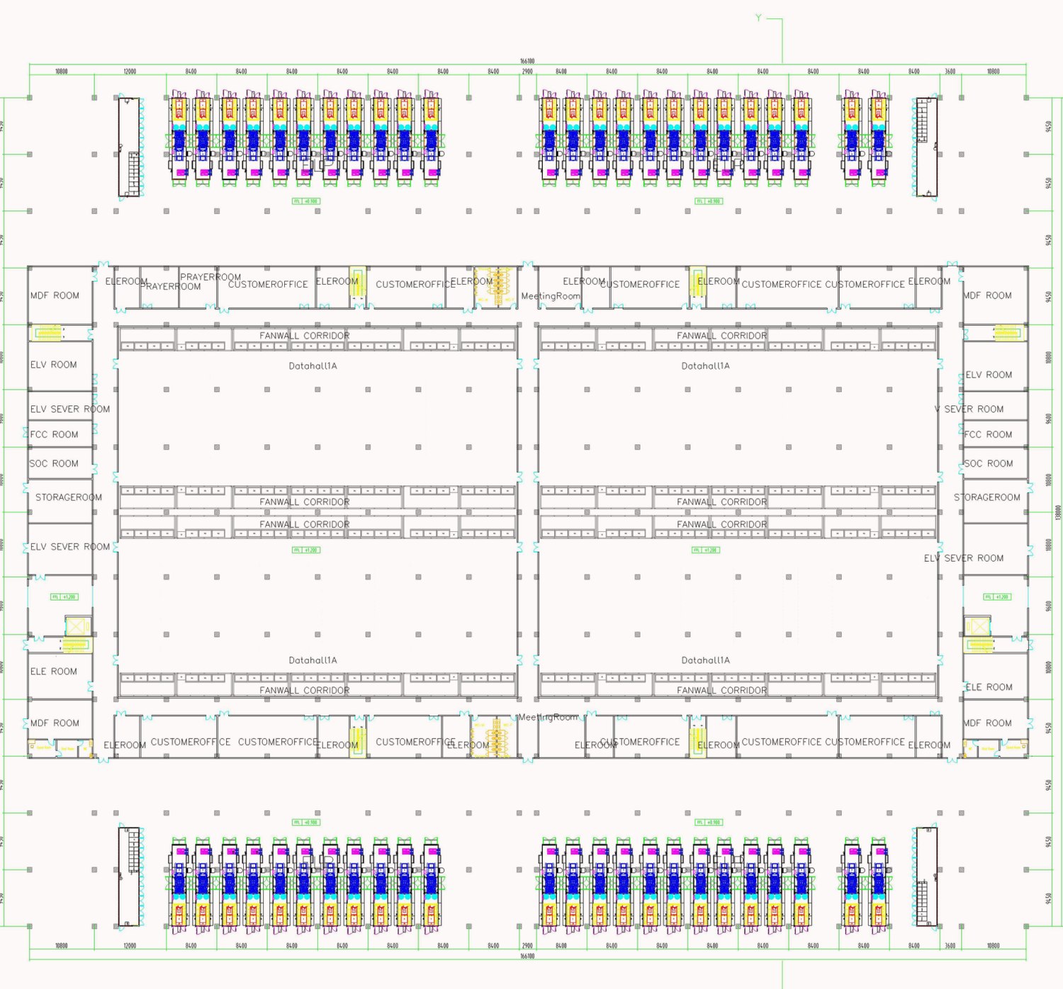
Step One
Whatever you already have. An architectural plan with room names and grid dimensions is enough to start on. You do not need a structural design, and you do not need to have decided on a frame material yet.
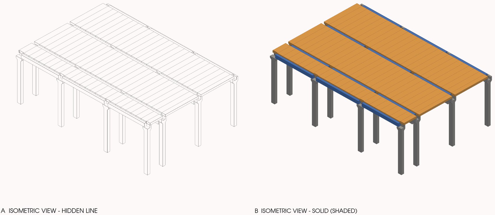
Step Two
A typical bay, built as a solid before any of it is drawn. Column, corbel, beam and precast slab system, in the sizes we would actually cast, so the framing is checked as a piece of building rather than as a set of lines.
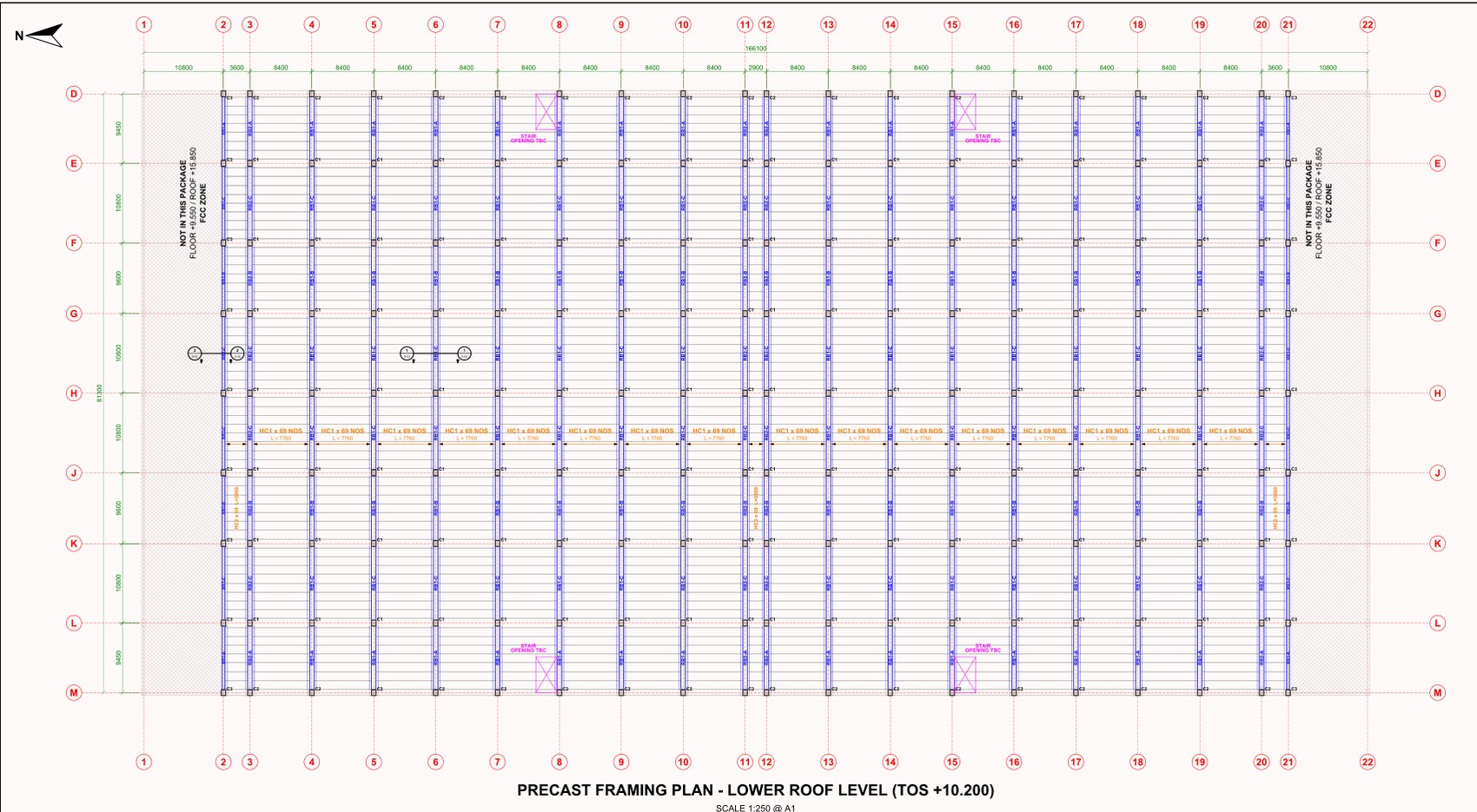
Step Three
Every column, beam and slab set out on your own grid, with member sizes, piece counts and the zones we are not pricing marked as not in the package. It is enough to take a view on cost and on programme.
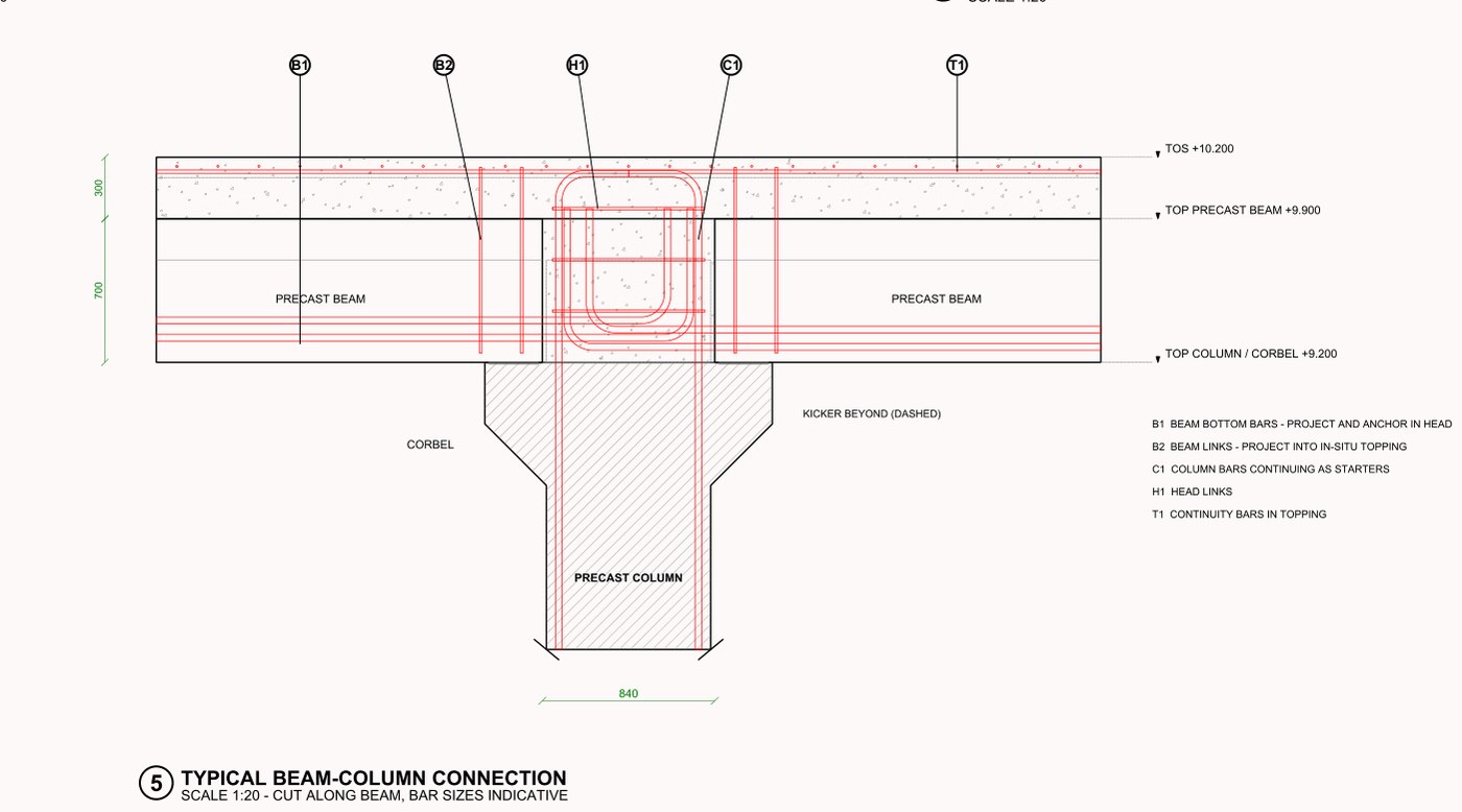
Step Four
How the beam sits on the corbel, where the bars run, what arrives cast and what is poured on site. This is the part that decides whether a scheme can actually be built, so it comes with the plan rather than after it.
All of it at no cost and with no obligation. If the answer turns out to be steel or cast in-situ, we will say so.
Send the precast drawings or the tender documents. We will come back with a price and a delivery programme.
Request a Quote